Below is the original factory Tap-Exp. schematic, now available for download, so that you can build your own Tap-Exp.!
Click the image below (or click HERE) for a full-size downloadable file.
Notes:
-Switch is a Normally-Open Momentary Contact type.
-Designed for use with Mr. Black stereo effects pedals featuring our proprietary "TAP/EXP" input.
-We DO NOT have the resources to provide ANY further technical data, support or advice/input on the schematic below.
-Jack Deville LTD./Mr. Black pedals is not responsible for unpredictable/undesired behavior resulting from the use of this schematic.
This circuit and schematic is NOT licensed for commercial use.
Please give cred where cred is due and enjoy life!
Play loud!!
]]>Heaven’s Gate is a unique, specialty reverberator, and as such, it was designed following a somewhat “unconventional” approach and methodology. Let’s take a moment to walk through the simplified (and I mean HIGHLY simplified) block diagram below. (Bypass system, power-supplies, all filtering, LED indication, etc. have all been omitted from this diagram in an effort to provide only the information necessary for a solid understand of the basic operation of the circuit.)
So lets get right into it, eh? (click the image below to open a high-resolution version in a new window for reference)
We’ll work straight through in a pretty linear/controlled manner, starting with...
Our input stage (Primary Input Driver as detailed above) is pretty simple and straight-forward, and is also pretty easy to understand:
The Heaven’s Gate input driver is a simple and robust input-driver (providing an intentional input impedance of approximately 500KΩ, such as not to load down passive guitar pickups, while maintaining the ability to accurately receive low-impedance output signals from active pickups, keyboards, and other alternate input signal sources) that translates our raw electric guitar/electronic-instrument/signal output to the signal and strength required to push our incoming signal(s) everywhere they need to be, at the correct levels and strength required for all the tasks downstream. We can see, our input driver provides strong, solid and continuous input-signal(s) to three basic blocks:
Let’s break down each of the three blocks being fed by our Primary Input Driver…
The Dry Output Driver is about as straightforward as they come. This is our dry signal driver, which retains our un-adulterated input to be later mixed, and subsequently output from the system (after mixing and all that stuff).
For simplicities’ sake, our Input Signal Detector has been drawn as a single circuit-block with the Trigger control shown beneath the circuit block. This portion of the circuit is responsible for creating the signal that determines when our reverb-gate engages and disengages.
The Reverb Engine is where our actual reverb is created, augmented, and finally delivered to our Reverb Output Driver (which is controlled by the Reverb Amplitude Control, driven by the Input Signal Detector). The Decay control determines the length of the reverb tail as generated by the Reverb Engine, and the engine’s output is fed directly to our Reverb Output Driver. (The Reverb Engine itself is extremely complex and has been reduced to a single block for simplicities’ sake.)
After sensing what is coming in from our Primary Input Driver and Trigger control input, our Input Signal Detector determines how we’d like our gate to respond and react, and then sends the appropriate signal to our Reverb Amplitude Control. The Reverb Amplitude Control then sends a signal to our Reverb Output Driver which controls and sets the output amplitude and timing of the Reverb Engine, which is later mixed by our Final Output Mixer and subsequently delivered to the output of the pedal. (More on all that shortly.)
Our Reverb Output Driver receives its control signal from our Reverb Amplitude Control and determines how much, and when reverb is sent to the Final Output Mixer based on the way our Trigger and Decay controls are set.
So far, this is a pretty straight-forward and simple arrangement, right? I know there’s a lot happening all at once, and these things can get confusing pretty quickly, but hey, the engineers at Mr. Black did all the “hard stuff” for you, so you can just kick back and enjoy all the sensitive ambience the Heaven’s Gate gives you without having to spend a bunch of time mucking about with the inner-workings and details.
From the outputs of our Reverb Output Driver and Dry Output Driver, our Final Output Mixer receives these two inputs, and with the configuration of our Wet/Dry control, outputs the signal mixture we want-- determined by the position of our Wet/Dry control. (This control, like many details in this diagram, has been grossly simplified in an effort to keep the diagram easy to read and understand.)
One thing to note is that this control actually “works backwards” from what you may expect, in that as the control is advanced (towards the 100% wet extreme), it is actually removing more of the output from the Dry Output Driver instead of adding more signal from the Reverb Output Driver. This control has been meticulously designed and balanced to provide a 100% dry / 100% wet output mixture when set to the center, and 100% dry OR 100% wet at either respective extreme, without any losses during the transitional positions. (Easier said than done!)
From the Final Output Mixer, we can then send our signal directly to the output jack and into our amplifier or next effect in the chain.
Now that we’ve covered the basics of Heaven’s Gate's internal function and operation, let’s talk about how you can quickly and comfortably incorporate this wonderful device into your signal chain, how to get the most out of it, and why you would ever want a specialized device like the Heaven’s Gate. Please, continue…
We already know that Heaven’s Gate is a gated reverberator, but what exactly makes a gated reverberator different, or potentially “better” than a conventional reverb pedal? Well, the answer to that concept is strikingly simplistic.
A gated reverberator offers an entirely new approach to including and employing reverb when building your tone. Reverbs are known and regarded for their obvious characteristic of making your sound “big” and full, and boy oh boy do they deliver! Especially dramatic and engaging reverbs (like the Mr. Black SuperMoon for example. :P).
However, one concern that often presents itself when adding any type of reverb into the signal chain is the dreaded “wash” which can make an incredible tone not only dramatic and powerful, but can also “smear” and “cloud-up” the full tone, and in its worst case, reduce the entire composition to a messy wash of sound. This is even more pronounced when a big tone is included in a passage or piece with sharp/abrupt stops and starts (think double-stops, break-downs, high-gain leads and the sort). Herein lies the true power of a gated reverb.
Because a gated reverb, by nature, disappears when you stop playing, it becomes nearly impossible to unintentionally create “the wash”, and as such a gated reverb can keep your tone and expression clean and clear, while adding the explosive, dramatic and powerful “extra” that only a nice reverb can give you. This is where gated reverb really shines and provides what conventional reverbs cannot; by allowing you to produce expansive, powerful and explosive moments while retaining the ability to cut the reverb tail off sharply accentuating the stops and silence required for breathtaking punches of sound and powerful, soaring leads. With a well dialed (and designed) gated reverb, the impact is increased ten-fold. Lucky for you, the Heaven’s Gate is both well designed, and easy to dial in.
Now that we’ve got a basic overview of the inner workings of Heaven’s Gate, lets talk about:
Heaven’s Gate is a deceptively simple pedal to use, and this is no happy accident; a lot of care and attention was put into realizing and delivering a simple, composed, and refined control interface capable of affording a wide range of sonic characteristics, and above all: delivering a damned good reverb when called upon.
Dialing in the Heaven’s Gate is sure not rocket surgery, but the process is very personal and one person’s settings may be radically different than the next.
What helps me visualize how each control affects the output and operation of Heaven’s Gate is to view each control as:
I’ll always recommend beginning with the Wet/Dry control set to high-noon as a baseline (we can trim this to *just* the right spot once we’ve got our Trigger and Decay controls set right where we need them, but for dialing in the Trigger and Decay, noon is a wonderful sounding board).
With the Wet/Dry control set at noon, we’ll get equal parts dry (plain/original input signal) and wet (reverb-only signal), mixed evenly. This will allow us to hear what we’re playing while also hearing the reverb we’ve generated, and allow us to get our Trigger and Decay set just how we like.
Trigger is a very “personal” control as it responds directly to You and Your Approach, and not everyone will set this control identically. I recommend starting with the Trigger control set very low (perhaps even minimum) and playing your instrument as you normally do, with your instrument output volume set to where you most commonly leave the control while using a “standard for you” attack and delivery. Gradually increase the Trigger control until you can no longer hear a change in the immediately delivered reverb level when playing normally (familiar operators may even set the Wet/Dry control to maximum so that they *only* hear the reverb signal). The idea here is to get the trigger to engage and disengage with you and as such, compliment your personal playing and attack.
Once our Trigger is tuned for us as individuals, we need to set our Decay control, and luckily, that’s a whole lot easier than dialing in our Trigger. While not as critical/delicate as the Trigger control setting(s), the Decay control allows you to tailor the density/intensity/length of your reverb impulse/explosion, and as such, fill in exactly how powerful your reverb impulse is.
Simply start with the Decay control at its minimum setting and begin playing as you normally would, but this time, let your notes ring out and pay close attention to when the reverb dissipates and approaches near inaudibility. Gradually increase Decay until you find that sweet moment where the reverb tail melds with and compliments your playing, while simultaneously subsiding *before* your next note. You may find it helpful to play extra hard and stop abruptly while configuring this control.
Many players like to trim this control to the specific song or passage that calls for that extra accentuating burst. Restraint will be your best friend here, and the trick is to not get greedy or indulgent by immediately setting the Decay to maximum. Shoot for *just* enough Decay to make the passage glisten and glow, without adding so much Decay that you approach wash-potential.
The last piece of the puzzle is configuring our Wet/Dry mix level, and this is truly a classic case of: What You Like. Good ol noon o’clock is always a safe bet, and you may even prefer dialing back the Wet/Dry control to about 10:30 or 11:00, for a more tasteful and less-ostentatious effect (this is frequently a great approach for clean, clear, uncluttered high-gain leads which demand precise articulation and singing note definition), but we all know that fantastic and illustrious sounds are often found with extreme settings (in this instance: a 100% wet-mix). Ultimately, you’ll find just the right mix by beginning at noon and trimming either direction after a few moments with Heaven’s Gate engaged.
And that friends, is the basic operation and configuration of the Heaven’s Gate - Gated Reverberator! Heaven's Gate was designed and intended for specialty applications and uses, where only *just* the right effect will do, and while not necessarily a common or general pedal, boy howdy does the Heaven's Gate do what it does well!! Wanna watch some videos, read the manual and see the pedal? Just click HERE or on that beautiful pedal.
As always kids: Play louder than you believe you should and don't forget to Rock N Roll!
Peace, Love and Hair Grease.
-Mr. Black
]]>I've got a lot to say here, and I'll do my best to keep it as concise and direct as possible; with that said: I am CERTAIN some people are not gonna like what they read here. FUCK IT. I've never been one to "go with the flow," and I have always caused trouble, wherever I am. I believe this article is gonna ruffle some feathers, soil some garments, and stain some egos, but sometimes the truth isn't as shiny and pretty as many would hope it to be. So let's get into it.
As you may be familiar, the vast majority of us were born with two ears, placed on either sides of our heads. I'm no biologist here, but I have found that one of the key benefits in having two sound inputs (a left and right if you will) to my central nervous system is the ability to locate a sound source with respect to my position in the physical world I am in.
That is to say: I can tell when someone is walking/talking/producing some type of sound to the right of me, behind me, to the left of me, or directly in front of me, as well as all the fine gradients in between, just by paying attention to the source of the sound. My brain calculates the rest and tells me where the sound is coming from automatically. Yup. That's what two functional ears and a minimally damaged sensory input system will afford you (or me in this case).
Well, in 2017 we started making stereo effects processors. And here's where things get fun and begin to get dirty (that's half the fun). You see, when we say we make Stereo Effects Processors, we actually mean we make STEREO EFFECTS PROCESSORS Not some fake "I can't believe it's not mono" bullshit, I mean actually Stereo, with TWO separate audio paths. And there is a difference as we will get into and detail here.
Let's start by having a quick look at the most basic Stereo (or True-Stereo as we call it) process/signal path.
In drawing below we have the most basic elements of a True-Stereo signal path:
Walk with me through this one. It's pretty simple.
An instrument is plugged into the LEFT INPUT jack and if no instrument is plugged into the RIGHT INPUT jack, the signal at the LEFT INPUT jack is automatically applied at the RIGHT INPUT jack, and subsequently the RIGHT INPUT DRIVER circuit (Pre-amp circuitry has been intentionally omitted from these illustrations to keep things as simple as possible; I don't wanna hear any bullshit about signal loss from splitting signal without proper drivers/impedances etc. I FUCKING KNOW. I design this shit for a living.).
Signal then flows through the left/right driver circuits and into their respective effect processing, then to their respective output drivers and finally to either the left or right output jack.
Pretty simple, right? This is TRUE-STEREO. We have TWO independent signal paths. Not the fake B.S. we will see shortly which is often marketed and sold as "Stereo." Let's keep focused on TRUE-STEREO for a moment longer.
The illustration above is the basic concept, but we've omitted any dry/un-effected signal. The illustration below shows the same TRUE-STEREO process, but now includes our dry support circuitry.
It looks pretty darned similar, except we have added in parallel dry processing for BOTH left and right channels, as well as summing circuits for each, and they are INDEPENDENT from one another. That is to say: Left and Right DO NOT MIX unless there is only one input source (left is primary input), which still produces independent processing of the left and right channels.
This is True-Stereo. Not fake-bullshit-faux-stereo. This is actually how a stereo system works, and that is very important. Burn this system into your mind. It will help a lot when planning and troubleshooting your stereo rig.
This system is largely how Mr. Black stereo pedals are designed and executed. We'll cover our own products in detail a little bit farther along in this article.
Let's move on to something all too common: NOT-stereo processes marketed and sold as stereo processes.
Here we see what is often marketed and sold as "stereo," and to it's credit, there are two inputs and two outputs, but what is between those interfaces makes, or in this case, breaks it.
Ladies and gentlemen, let me introduce you to the Summing Dual-Mono process:
I know! It looks a lot like it could be stereo because it has left and right inputs, left and right drivers, and left and right outputs, but inside there is only one process creating the effect(s), after the left and right signals have been combined together into a mushy, blurry, brownish-grey stew (sounds great, huh?). Once we've created our gruel, we can then slop it into both outputs; because stereo is two outputs, right? Fucking hardly.
The above illustration is the basic system often marketed as stereo, when really it is not stereo at all. It is dual-mono at best. But, we could doctor it up a little so it seems more "stereo-ish" to those really inquisitive ears out there. Check it:
Now we're a little closer to a true-stereo system, because we have independent left and right Dry signal paths, but our effect processing is still happening in mono and just being split at the end to mimic a stereo process! I call 'em like I see 'em and that is NOT a stereo process: That's BULLSHIT!!
Believe it or not kids, the VAST majority of fancy-schmancy boutique "stereo effects" are designed this way. Some don't even isolate the dry signals as well as this illustration.
To say I was shocked to discover this is an understatement, and I didn't believe it at first, but with the right questions to the right people I verified it to be true as the blue sky above. Sad but True (but not True-Stereo, mind you).
Now, I'm not gonna name any names here (you can contact your favorite manufacturer and ask them about your favorite product), but this is VERY common, and is also VERY BULLSHIT.
Here at Jack Deville LTD., I design the Mr. Black line of pedals from the ground up, and when I design stereo pedals, I actually design true-stereo pedals with TWO independent audio paths. Mono pedals are mono, duh.
At the time of this article, we have three stereo pedals in the line-up: The Tapex 2, the Supermoon Eclipse, and the Stereo Vintage Ensemble; each work a little different from one another, with some neat tricks occurring internally. Here's a quick little break-down of how they each operate (I am negating switching, presets, expression controls and all the other auxiliary circuits in an effort to keep the drawings simple and easy to understand). With that said, here we go!
While the Tapex 2 is a true-stereo process and circuit, the echo is only sampling/recording from the Left (primary) input. The Right channel is a straight pass-through with an echo at half time mixed in with the dry right source.
The SuperMoon Eclipse is a True-Stereo effect processor with two fully independent signal paths and two simultaneous and complimentary reverbs sharing controls. I repeat: THE SUPERMOON ECLIPSE IS A TRUE-STEREO REVERB. You can literally run two instruments into each of the channels and they will remain separate, sharing only in controls.
PLEASE NOTE: The SuperMoon Eclipse's left and right outputs are 180° out of phase from one another, which enhances the stereo spread. We have found this to cause problems when fed directly into a summing dual-mono processor (1 + -1 = 0).
If you have experienced your Eclipse "killing" your other "stereo" pedals (which it does :P), know that the pedal being killed is NOT true-stereo and you can easily negate this by inserting a pedal that inverts phase (Such as the ZVEX Super Hard-On or EHX LPB-1, set to unity volume) directly after the right output, before the input of your summing dual-mono processor, or by simply putting the SuperMoon Eclipse last in your stereo effects chain.
The Stereo Vintage Ensemble works much the same way that the Tapex 2 does, except it is a fantastic chorus pedal, rather than an echo.
I truly hope this article has been useful and informative for you, and thank you for taking however long it took you to read it. There are times that marketing overtakes and surpasses fact, and in the case of buzz words like "stereo," copy sure can be misleading. Here at Mr. Black, when we say True-Stereo, we actually mean True-Stereo.
]]>Half of her body was completely paralyzed.
This made her speech difficult, and actually moving nearly impossible. In the days to follow, she received life changing news and was diagnosed with Multiple Sclerosis (MS); a permanent, degenerative nerve disease. For more information about MS, please click here.
My mother, as well as my best friend’s mother, and countless other mothers, fathers, sons, daughters, grandmothers, grandfathers, teenagers, adults and everywhere in between have given themselves to the pursuit of an actual cure for those not yet diagnosed, via multiple invasive and non-invasive tests, studies, medications and treatments.
And it is a BRUTAL disease.
I’ll spare you the details, but over the last 18 years, I’ve watched my mother’s health oscillate and her physical condition improve and relapse. She can currently walk well, and live a “normal” life while she is involved in a long term study following a strict regimen of various chemical and physical treatments. Much of the funding for this research is provided by the National MS Society, a non-profit organization devoted to the pursuit of a cure for MS.
Last year, a close friend of mine asked me if I would sponsor her in a fundraising event for the National MS Society. Guess what my answer was.
This year, I wanted to do a little more than I was able to last year.
With that said, we have built 100 Special Edition SuperMoon Limited reverb pedals, which are now available for “purchase.” I place the word “purchase” in quotations because these pedals do not carry a fixed price, and 100% of the proceeds from their sales will be directly donated to the National MS Society via sponsorship of my friend’s fundraiser ride.
Yes. You read that correctly.
100% of the proceeds are donated.
100%.
Only you can decide what your budget affords. While I encourage you to select a higher price point than our standard $179.95, I understand if that’s not within your budget right now. At the same time, we are not making a dime on this project. Again, 100% of the proceeds from these 100 units is going directly to the National MS Society. All of it.
Why?
Its quite simple really.
I think you see where I stand on this one.
With all that said, I’ll reiterate the basic facts and bullet points of this limited run.
The National MS Society has improved the lives of countless people across the USA, including my mother and my best friend’s mother. With any luck, an actual cure will be developed for this curse and someday, people will no longer suffer from the effects of this cruel and terrible disease.
If you are interested in donating directly to my friend’s fundraiser, you can do so here:
http://main.nationalmssociety.org/goto/Erin-RidesAgain
If you are interested in donating directly to the National MS Society you can do so here:
http://www.nationalmssociety.org/Donate
I encourage you to stop and hold the door for the next person you see entering a building. Share your umbrella when it rains. Buy a homeless guy a sandwich. Basically, be the best person you can and do the best you can with what you’ve got. Its really all any of us can do.
This is Jack, owner/designer/whatever of Mr. Black pedals saying:
I hope you enjoy these pedals and the purpose behind them. Be good to yourself and the next person.
]]>
Auction runs 03.03.2016 - 03.10.2016
Let's not kid ourselves here, this isn't a particularly "special" or "novel" design; it is however, VERY good at what it is designed to do, and if you look closely, you'll see a few really nice, dare I say "elegant" design practices that can be applied to any number of audio circuits. So, without further ado, I give you the original Boost Tiger factory schematic.
This circuit and schematic is NOT licensed for commercial use. Please give cred where cred is due and enjoy life!
Please note: we DO NOT have the resources to provide ANY further technical data, support or advice/input on the above schematic. When built according to the above schematic with quality parts, this is a BANGER of a circuit. Party on and PLAY FUCKING LOUD!
]]>All 50 ThunderClaw pedals for the Pixie Project sold by 10:47pm Oct. 30, 2014!!
This is wonderful news and on behalf of the Pixie Project, we thank you! We still have to pull reports and push buttons on calculators to determine the total raised, but I have a feeling it will be felt by all involved (and to be involved) with the Pixie Project.
Special thanks to Jesse L. who kicked in at the top level of $400. Dude, the world needs more people like you. Next time you're in Portland, beers are on me personally.
But it wasn't just Jesse who opted to donate more than the minimum, and that's really something special. You know who you are, and we'd like to personally thank you for going above and beyond.
Even the base donation level helps a ton, so don't get it twisted and think we don't appreciate everyone who scrounged together what they had to support the Pixie Project.
Since we sold out so quickly, we've had a few folks as how to donate to the cause. Well, turns out its really easy. The Pixie Project has a special donation page and because they are a 501 (C) (3) non-profit, your donation is fully tax deductible. Click this link and get happy:
http://www.pixieproject.org/supportus/
We've got a bunch of pedals to ship so you'll have to excuse the quick nature of this Straight Jive entry.
Day 1
-----------
9:02 a.m. - Kirk arrives at Jack's house and is happy to find that he has recovered from the malaria he was suffering from the previous two days.
930 a.m. - We pick up Justin and quickly hit the road. Music Choice: Big Business - Here Come The Waterworks
10:13 a.m. - We stop for coffee at a drive-thru Starbucks. Justin says "fuck starbucks" and we promptly drive him to a drive-thru Dutch Bros. We talk about the tattoo artist who has the dick tattoo market locked down. Not tattooing on a dick...but tattooing dicks on other parts of the body.
11 a.m.-1 p.m. - Lose an hour in magical vortex that is I-5
1:17 p.m. - Make friends with the locals/yokels of Southern Oregon. We are getting homesick already.
2:00 p.m. - We see a Red-tailed Hawk and a gigantic Bald Eagle within a few minutes of each other. We talk about nature and Justin's former job scaring birds off the tarmac at PDX airport.
2:30 p.m. - Tortilla chip hits the iPod causing "heat 4 yo azz" by Celly Cel pop onto the stereo.
2:43 p.m. - Kirk tries to explain the plot of Death Race 2000 to Jack. Fails miserably.
3:02 p.m. - California border. How much do these guys that ask about fruits and vegetables make? Too much we presume.
3:30 p.m. - Kirk orders largest burrito any of us have ever seen.
3:50 p.m. - Kirk immediately regrets eating entire said burrito.
4:20 p.m. - You know the deal...
4:21 p.m. - Pulled over by the California State Highway Patrol (you can't make this stuff up)
4:30 p.m. - Change collective underpants. Music Choice: Dead Meadow - Feathers
5:30 p.m - 8:30 p.m. - Music Choices: High on Fire - Death Is This Communion, Polvo, Kylesa - Static Tensions
8:30 p.m. - Arrive in Oakland. Staying with our friends Brian and Amy at their beautiful loft. Red beans & rice. Beers. ChinatownX
Days 2-5
------------
We started our epic road-trip to sunny Anaheim with every intention of keeping up with daily accounts of our shenanigans. Unfortunately, beers, business and fun took over and the dull ringing in our ears and heads made it impossible to keep up with this "tour diary" on a daily basis. We're sorry. You can schpank us.
Day 2 started with an excellent breakfast cooked by our wonderful hosts Bryan and Amy. We set out in the Crown Victioria towards central California. Although we had complained about the vortex in Southern Oregon the previous day, nothing compared to the 6 hours between Oakland and the Grapevine. Pure. Unadulterated. Boring.
We managed to cut the monotony of the open road by listening to awesome tunes and running over as many tumbleweeds as we could...and dick and fart jokes...always the dick and fart jokes.
We arrived in sunny LA just in time for rush hour. Yay. We managed to make it to Anaheim relatively unscathed. Checked in and unpacked and headed up to the "Sheraton Club Level" (which is special apparently) for free cocktails.
Shortly thereafter we headed down to Earthquaker Devices bowl-o-rama after-party to check it out. We met up with our buddy Philippe from Caroline Guitar Co. and hung out with the ZVex, Earthquaker, Walrus Audio and Fairfield Electronics crews. It was a blast. We also met our new favorite person Kilyn from Walrus Audio. He's kinda like the little brother none of us ever had...lucky for him.
We woke up the next morning ready for the long trek through the monstrosity that is NAMM. We felt like champions from the night before. After walking approximately 22.3 miles collectively, we called it quits and prepared for another night of fun ahead by heading to dinner.
By the by, has anyone ever noticed how big Cheesecake Factory's menu is? There's 6 pages specifically devoted to chicken. Insane.
We headed over to Walrus Audio's hotel where they kidnapped us in their windowless van and drove us to this place. We only obliged because of the enormous bottle of Jim Beam they provided.
We ended the night with our friends Philippe, Kilyn, Chelsea and Patrick. Don't they look happy?
We woke up the next morning and headed back towards home. It was a quick trip but one that we will never forget. We made a lot of new friends and met a lot of our peers. We also had some seriously great fun and look forward to next year.
Until next time,
Mr. Black & Co.
]]>To make it easy on ya, we made a video. Dig it, and visit Circuits to Cure Cancer to learn more about who's who, what's what, and just how you can do yo thang:
If you haven't guess it already, this edition of Straight Jive is going to discuss some power supply theory, the "ideal" power supply, and the harsh realities of life as a musician-- at least insofar as DC supply voltage for your 9V effects pedals. All that other shit, sorry man, you're on your own.
So...
In a perfect world, a 9V guitar pedal (like say, I dunno... a SuperMoon?) would receive a perfect nine volts (no more, no less) of direct current, with an ideal current supply delivering said current. This would be bitchin. We could completely eliminate our power filter circuits (think otherwise? TAKE YO ASS BACK TO CLASS), radically lower the noise floor and deliver a product that would never, ever, ever in 20 million-bajillion-thousand-giga-years (note: a giga-year is bigger than a normal earth year) fail or show any sign of electronic fault. That would be fucking killer.
Sadly, nothing in this world is perfect, but there is a very real beauty in that fact. I like some of my tattoos because the fill goes outside the lines; some spots chose to scar, blow-out and shift as I've aged and worn. Music sounds good on a record, because there's imperfections in the playback and the recording sounds a little different every time you hear it, just like a real, live band. Perhaps we should embrace the shortcomings of our real world power supplies and shun the notion of the ideal supply? Nah. Fuck that. I want good power.
Back to the ideal supply: the closest we get to an ideal supply in everyday practice is a battery. Chemical storage of electrical charge. That's what a battery is, and also why I think hybrid cars are just another disposable razor, but that's a whole 'nother topic.
A typical battery you would use in a guitar pedal is comprised of six individual energy cells, each developing a nominal 1.5VDC across its terminals. When strung together in series, the potential across the terminals simply sum, delivering the nine volts so many effect circuits are based around. This is totally killer, compact, and even relatively in-expensive. BUT! There's a major drawback: chemical degradation. Commonly known as a dead battery. Fuckin bummer man.
A battery is our closest approximation to an ideal supply because it just fucking delivers. I'm not gonna get into the physics and chemistry behind dry-cell theory and operation, there just isn't time for all that, but I encourage you to check it out. It may change your perspective on a few things and nourish some creative ideas!
Back to the battery: it just fucking delivers. A battery kicks out as much current as it can, slowly depleting its reserve storage charge-- read: dying. The beauty in this short-lived flower is its purity: there's no rectification taking place. There's no switching happening. Electrons just line up and march. They march to push, then they march on. Then they die. Lame.
But seriously, think of a battery as the closest practical approximation of an ideal current source you can get your greasy little mitts on, because that's about as good as it gets. At least for our purposes.
As you probably know, the power in our walls is delivered in the form of Alternating Current. Really, there are some advantages to delivered alternating current, but for our lovely little effects pedals, we want direct current! So, we've gotta manipulate the AC and make it DC. Or at least a close approximation to DC. LET THERE BE ROCK!!
I wish I had the time to discuss common rectification techniques and the advantages some systems have over another, but I wanna stay on track here and we'll just look at full-wave DC rectification.
The basic idea is to manipulate the AC supply into only providing positive (or negative depending on the reference point) voltage. It is quite a simple concept really, kinda like primarily using the downward-pressure generated in a reciprocal combustion engine. Of course, there are losses here, but we're humans. If we cared about wasting energy we would probably not be relying on electromagnetism for energy generation would we? If you're really curious about the inner workings of a full-wave bridge rectifier, you should check out Wikipedia's entry on it. Hyperphysics has a pretty good article as well. Read them and change the world.
Once we've got our AC successfully rectified into modulating DC, we've gotta do our best to smooth it out and fill in the gaps (AKA: get rid of as much fucking noise and bullshit as possible). Luckily, we've got some pretty useful circuit elements than can help us with that, namely the capacitor and the inductor. More often than not, you'll find capacitors over inductors, largely due to cost and the physical constraints of inductive circuits. This isn't to say they aren't out there, but they much less common than capacitive filters.
These concepts are the basic building blocks of the familiar, often disdained wall-wart. Everybody has a few shitty ones lying around. You keep thinking it'll work, but its just a noisy piece of shit. Do yourself a favor: get rid of it. Its not serviceable and it ain't gonna fix itself. Lower your blood pressure, your hairline will thank you.
Most wall-warts are just these simple circuit blocks: a bridge rectifier and a simple filter to smooth out the modulating DC into "basically DC." Often times, "basically DC" is good enough for the job. An alarm clock? Totally fine. You're gonna hit that thing as hard as you can and try to break it. It doesn't need a fancy-schmancy super-clean-ultra-linear-power-supply circuit. Just something to get the job done and keep you from being late to work. But our guitar pedals? Well, we need a little more than "basically DC."
One of the neat things about guitar pedals specifically is that they are independent from one another, and their respective power supplies. In fact, they're so independent, that lots of guitar pedals have their own power circuits built right into them. Not the type of power circuit that generates power, but they type of power circuit than manages the incoming power. After all, a good manager is key to a successful team! Now I can speak for everyone, but I design the power circuits around here, and I can tell you that careful thought and consideration is given to these deceptively simple circuits.
Now, it may seem obvious, and for some people the low-hanging fruit of increased capacitance is the natural solution. Lets stop for a sec and talk about why someone would think about increasing capacitance.
I think the line of thinking goes a like this:
We've got dirty power coming in. What to that use to clean up the power? A capacitor!! So if we just add capacitance, we'll clean up that power! Jeez. I'm a great engineer.
Well, kinda. While increasing capacitance does have its place, its not the be-all-end-all method for cleaning up shitty power and ensuring a quiet pedal. If it was, then you'd see huge fucking banks of capacitors in mass-market guitar pedals. It is true that increasing the capacitance of the power circuit will "catch" lots of bullshit on the power rails and further smooth out "basically DC" power, but everything at its cost. Those caps don't ship charged, and they certainly don't hold a charge for all that long (unless the Thévenin equivalent is enormous, in which case you wouldn't care about a power supply because a battery would last two lifetimes). What that translates to is that a bit of current will be used to "charge up" the suggested massive capacitor bank and while it may help provide a layer of insulation against ripple on the positive rail, it also places quite a demand on the supply to deliver a lot of current at initial power-up. If that supply is a battery, well, you just took a big bite out of the life-span of your ideal supply.
And you know what else? There's more.
A huge bank of capacitors makes the power delivery s-l-o-w. I mean d--r--a--g--a---s---s s---l----o------w. Tonally, the effect is a muffled top end, and a stiff, gummy feeling to the circuit. Hey, maybe that's what you want. If so, Mr. Black just broke you off with the secret formula for making dark, murky, molasses-uphill-in-january tone. LOTS OF CAPACITANCE.
Probably one of the easiest and cheapest ways to supply power to a number of pedals is the ubiquitous "daisy chain." This is how lots of us end up with isolated supplies. We buy a wall-wart for our favorite pedal because we keep replacing batteries and that shit gets expensive. But that wall-wart only provides power to one of our pedals, and we like to use A LOT of pedals. So instead of buying individual wall-warts for each pedal and a big-ass power strip to plug all those wall warts into, the guy at the guitar shop sells us a daisy chain that we plug our wall-wart into, and then plug each little end of the daisy chain into our individual pedals.
Works great! Except we've got that one fucking pedal that makes a shitload of noise on a daisy chain. You know the one's I'm talking about. And, when we use that polarity inverter adapter (because we need a fucking adapter to use this damned pedal) it wipes everything out and nothing works. Not only that, but we've got this tangled mess of cables, wires, half-smoked doobies, parking lot grime, cigarette butts and all kinds of other bullshit making our board look like something that came out of one of the shitty pawn shops on the wrong side of town. Epic bummer.
To make it worse, for some reason, our amp sounds dull and shitty. Well, this may be the result of excessive capacitance on the power rails.
I personally think reduction in total capacitive load on the power rails is one of the benefits of employing an isolated supply. Maybe this is why they have become popular. There are other reasons as well of course: inverted ground schemes, and of course: NOISE REDUCTION! Right? Well... lets just see how this article shakes out.
Back to capacitive reduction!
When capacitors are placed in parallel, they form a bigger capacitor. Not physically! But functionally. For example, if you have a 100 microfarad capacitor (abbreviated µF) wired in parallel to a 47µF capacitor, the total capacitance in the network is 147µF; 100µF + 47µF. Easy peasy, like greasy fleece. Well, this is one of the shortcomings of a "daisy chain" configuration, especially if you've got a pedal designed with a massive bank of filter capacitors across the power rails.
Isolated power supplies ensure that each power source is separate (or isolated) from one another preventing huge capacitive build-up. Not only that, but you can have inverse polarity between units because the common rail (often called ground) is the only common power rail throughout the entire signal chain (or circuit)-- positive/negative supply is provided individually to each sub-circuit (pedal). Almost as if you had individual power cells for each pedal.
That means your tone is gonna be full, flexible, and not dark and murky and shitty. That sounds like a pretty good thing to me!
But, everything at its cost as you will soon see.
This is where things get real. The proving grounds, so to speak. I noticed this really weird thing a few weeks ago:
My good friend Philippe, one of the guys at Caroline Guitar Company, sent me a Maxon OD808. If you don't know about this pedal, it is green, it has three knobs and its got that "classic" overdrive tone. Oh yeah. Its a winner.
So the pedal shows up, and I plug it into my favorite little living room amp: an Orange Tiny Terror. I dial in a little bit of grit and hit the pedal to take it to the top. Well, I'm telling you, I got some fucking righteous tones, but I noticed something: I was getting a lot of extra noise! Could it be the new pedal? I turned the pedal off and the noise went down, but it was still there.
You puzzled yet? I was.
I knew the pedal was a buffered, electronic switching job, but that shouldn't matter, right? Well... I was so puzzled, I decided to figure it out. And I did. Check it out:
I dropped this pedal right onto my Pedaltrain Jr., which is furnished with a pretty bitchin "industry standard" isolated power supply. This power supply has eight isolated outputs, most of which can put out an impressive 100mA each! I have, what I consider to be, a decent little pedalboard setup. No, its not some fancy-ass boutique rig, but its a workhorse with isolated power. Its lightweight, practical and strong. Dude, its solid. But for some reason, I was getting a shit load of noise.
I don't know why, but my first thought was to try subbing in a cheap switching power supply and see if that changed anything. Mind you, I was only running the OD808. No other pedals used. Just guitar, OD808 and amp. Oh, and my fancy-schmancy expensive isolated power supply.
So I hook the OD808 up to the old power supply, a compact, $20 job that kicks out an impressive 1700mA. Would you believe me if I told you that the noise floor went down notably? Well, it did.
This strange behavior left me feeling weird and confused; a state I have become comfortable with, since I'm often confused, and always weird. So I did the most logical thing I could think of: I called Philippe to tell him about my findings.
Philippe and I chatted for nearly an hour and I explained the strange phenomena I discovered. He didn't fully believe me. Shit, I didn't. So I decided I would document my findings and pursue some research. Well, here we are.
I was so intrigued by this strange behavior that I brought the power supplies to the diagnostic bench and took some measurements. I put them bitches on the scope to see what I could see about the noise levels of each, and of course, that of a fresh 9V battery.
This is my oscilloscope. It is a 60MHz analog scope. Way more power than you need for guitar pedals, but hey, anything worth doing is worth doing to total excess, right?
This photo is a ground reference, establishing our base-line
I performed a total of ten measurements. Three sets of three, and one final comparison of a fresh 9V battery. The first measurements were taken with the scope configured as below. 20µS / horizontal division, 20mV / vertical division.
A photo of the initial configuration of the scope. The next three photos used these settings.
This is raw AC waveform taken from the isolated power supply's "normal" output.
You can see about 10mV of bullshit sitting on top of the 9VDC output.
This is the raw AC waveform taken from the isolated power supply's "variable" output.
With the variable output disabled-- switch in the "NORMAL" position.
A little more bullshit than the "normal" output.
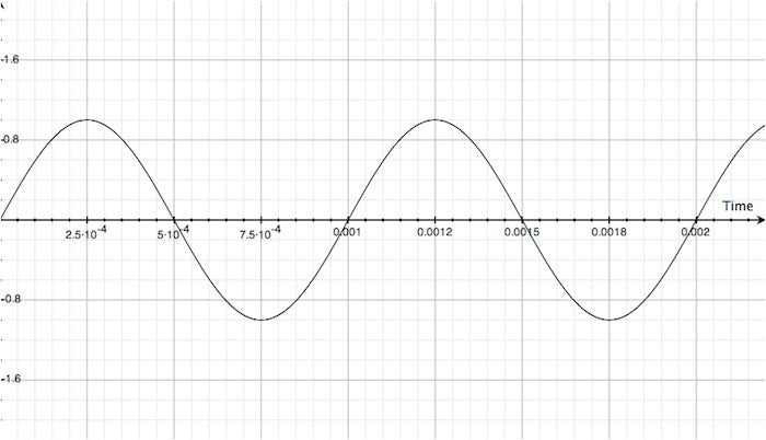
This is the raw AC waveform taken from the switching power supply's only output. It seems like it has a little less constant noise than the isolated supply, but you can see the spikes when the power supply switches. If my scope is dead nuts on, we've got a surge happening every 80 µS (about four vertical divisions between each spike at 20µS / division). Based on that figure, we can determine that we could have a small 12.5KHz signal sitting on top of our positive supply (0.00008S ^ -1, or 1S / 0.00008S).
In an effort to improve detail and really hone in on my findings, I increased the resolution of the voltage measurement. The scope has been reconfigured to display 10mV / vertical division as seen below.
A photo of the scope settings for the next series of measurements
"Zoomed in" a little, we can see that 10mV bullshit sitting on top of the isolated supply "normal" output even better!
Here's the "adjustable" output on the 10mV / division scale. You can see there's a little more noise than the "normal" output, eh?
Here is our switching power supply. Its actually looking like its got a little LESS noise than the isolated supply!
Minus that switching mark of course.
To really hone in, I took my scope to its most sensitive setting: 5mV / vertical division. For a little perspective, it would take 20 vertical lines to display one volt. One fucking volt. This scope can display 0.04V (40mV) across the entire screen at this setting. Here's a shot of the control panel for reference:
We are now on the 5mV / division setting: the most sensitive this little scope offers.
This is the "normal" output of the isolated supply. It is now really easy to see that' we've got nearly 10mV noise/bullshit sitting on top of the DC supply voltage on this output.
Whoa, baby! This is the "variable" output on the isolated supply, and I'm telling you, that is A LOT of noise.
Obviously, this is the switching supply at 5mV / division. It is actually generating less ambient/background noise than the isolated supply, BUT! it has that pesky switching spike every 80µS or so.
Now this info is all well and good, but we really need a reference dontcha think? I did. So I measured a fresh 9V battery with the scope on its most sensitive settings. Here is the result:
Even a battery exhibits a little bit of noise. A lot less than the measured power supplies, but still a little.
Just goes to show you nothing in this world is "perfect."
Well pictures are all well and good, but seriously, don't you wanna know just what this means to YOU AND YOUR AMP? I sure did. So I recorded each configuration. I even converted them into MP3 format so you can stream them live or download them for yourself to listen to in your reference library. You do keep a reference library, don't you?
All the sound clips were recorded as such:
Guitar (bridge pickup volume all the way down) --> Maxon OD808 (all knobs at noon) --> Orange Tiny Terror (settings below)
Recorded in Adobe Audition CS6 with a plain-jane Shure SM57
Well, you can draw your own conclusions here. Obviously, diming the amp increases the noise level substantially, but it also really brings the noisiest situations to the foreground.
I learned A LOT through this experiment and process, and I think I'm gonna be switching back to a cheap switching supply and selling that fancy isolated supply, since it doesn't really offer much to me and my situation.
I hope this lengthy edition of Straight Jive has been informative, useful and fun for you. It sure has been for me.
Until next time, peace, love and hair grease!
-Jack
]]>
Big hair, overstated eye-makeup, leopard print, mountains of blow, cheap groupies, and who could forget the image that has been burned into a minds and psyche (for better or worse): painted-on hot pink unitards with what looks to be a malformed potato bursting from the nether-regions of the lucky guy who shoe-horned himself into that unitard.
Lets not forget one of the most popular (and new for the time) effects of the '80s: the chorus tone.
This edition of Straight Jive will cover a little about the chorus sound, but most of all, we're gonna focus on exactly why the Double Chorus is the ultimate shit, why it sounds so much better than most every other chorus pedal you've played and how a guy who doesn't like chorus (like myself) can get down and boogie in his own personal unitard: a beat up pair of Levis.
A signal (your guitar in this case) enters the effect circuit and immediately encounters a short delay line. But this isn't any ol delay line. This delay line is special, like the finest columbian money can buy. Because unlike a big ol pile of blow, its modulated. What does that mean exactly?
What the effect will be doing is modulating the delay time, meaning that the time delay, td as we'll be referring to from this point forth, is continually changing: much like a rockstar's evening groupie.
The modulated delay is added to the un-adulterated signal (dry signal) replicating the sound that occurs when two people play guitar at the same time. Super neat! Now one rockstar sounds like two!! And what's better than two rockstars?
Two rockstars with four groupies.
Check out the picture below to get a visual on the action:
The brown line is our dry signal, occurring at td = 0S (real time).
tdThe blue line is our modulated delay line, centralizing around td = 0.01S (10mS delay).
Note as time goes forward (moving to the right along the X axis, the modulated delay line's td is changing.
When we mix these two signals together (literally combining the signals by adding them to each other) we get our basic chorus sound. Pretty easy, right?
The corny part is simple really. Everyone in the '80s wanted that amazing new tone. So everyone used it. Of course, that made the chorus sound a pretty iconic tone of the '80s, and all the corn-ball shit that went along with it (see the list in the first paragraph).
The boring part is where things get interesting (deep, man. deep). With only one modulated delay line, our ears can actually tune into the modulation that is occurring on the wet (modulated delay) signal and as a result, we hear the pitch change independent of the dry signal.
BBBOOOOORRRRIINNNGGGG.
Let's get one thing straight: chorus doesn't suck. Plain-jane chorus sucks.
And this my friend, is where things get rad. Epically rad.
The DoubleChorus is called the DoubleChorus for good fucking reason. Its not just a chorus pedal.
Its a DOUBLECHORUS pedal.
The heart of the Double Chorus is its chorus "engine" so to speak-- what is actually making the chorus, and how this super-mega-plus-plus-super-whammy-bagels portion of the circuit works.
While most chorus pedals combine a modulated delayed signal with a non-delayed signal, the Double Chorus combines two inversely modulated delay signals with each other, twice. Then mixes in as much of the dry signal as you want. From 100% dry / 0% wet to 0% dry / 100% wet. Right smack dab in the center of this (50% dry, 50% wet) you get a complex, massive and smooth chorus sound, without the typical warble and predictability to get from single delay line chorus.
Sound a little different? It is. And there's more.
We'll be referencing a little bit of trig terminology for the next section, but that's just the nomenclature. If the words confuse you, the pictures will make it easy.
Remember how the Double Chorus "combines two inversely modulated delay signals with each other, twice?" Here's an illustration detailing how it all works and why the Double Chorus sounds so goddamned tight.
Lots of shit going on, eh? Its really not as complex as it looks, but some careful examination will help break it down for ya.
Lets start by looking at the blue lines, herein referred to as "Chorus Pair 1":
You probably first noted that they are "opposite" one another, that is to say: when one goes up, the other goes down and vice versa. Well, you're spot on and for the trigonometrically inclined, we'll make some simple equations for those two lines: Sin(x) and -Sin(x) respectively. You see how this works now?
But there's a neat little detail that's not being shown in this simple two-axis illustration: the relative phase of each line (signal). See, if both signals were in phase with one another, we'd have some neat chorusing and vibrato happening, but it wouldn't be epic. It'd be a hair past regular, and frankly, Mr. Black pedals aren't "regular."
The two signals forming Chorus Pair 1 are actually 180° out of phase from one another, which means when they meet up (paths cross) they fully cancel each other out. ...kinda like a through-zero flanger... For a refresher on this process, dig this Straight Jive article.
So that's all neat and dandy, but what about when they're as far away from one another as possible (both waves at their "peaks" so to speak)?
Well, the short answer is: we have effectively created a "chorus effect" with two modulated delay lines rather than one. A "double" chorus, if you will; and even if you won't. That's pretty cool, but remember that twice caveat from "combines two inversely modulated delay signals with each other, twice?"
Remember the first picture in this series? Don't scroll! Here it is again:
We've added two more modulated delay lines ("Chorus Pair 2") and we can make some simple equations for those as well: how bout Cos(x) and -Cos(x)? Awww yeah. Now you're starting to see it.
See, Sine and Cosine are quite closely related to one another. In fact, they are essentially the same, with a 90° phase shift occurring between the two.
So we can say, for our purposes at least, that Cos(x) is 90° out from Sin(x). We can then infer that -Sin(x) is 90° out from Cos(x), since -Sin(x) is 180° out from Sin(x). We then can conclude that -Cos(x) is 90° out from -Sin(x), since -Cos(x) is 180° out from Cos(x), and thus -Cos(x) is 270° out from Sin(x). Isn't deductive logic fun?
What all this crazy shit means is that we have both a peak (high point of a wave) and a valley (low point of a wave) occurring every 90° (at 0°, 90°, 180° and 270°), which means we have two complementary waves (180° out of phase from one another) canceling each other out every 90° (at 0°, 90°, 180° and 270°), and thus we have two identical waves summing every 90°, after a 45° shift (thus at 45°, 135°, 225° and 315°). Confused yet?
Its a lot of numbers, degrees and shit to keep track of, but here's the breakdown of what your ears will hear from the delay lines during one complete cycle (phase angle represented with our good buddy theta, θ):
Phase Angle ( θ = ... ) |
Action |
θ = 0° | Subtractive TZF |
0° < θ < 45° | Chorus |
θ = 45° | Additive TZF |
45° < θ < 90° | Chorus |
θ = 90° | Subtractive TZF |
90° < θ < 135° | Chorus |
θ = 135° | Additive TZF |
135° < θ < 180° | Chorus |
θ = 180° | Subtractive TZF |
180° < θ < 225° | Chorus |
θ = 225° | Additive TZF |
225° < θ < 270° | Chorus |
θ = 270° | Subtractive TZF |
270° < θ < 315° | Chorus |
θ = 315° | Additive TZF |
315° < θ < 0° | Chorus |
Pretty rad pattern we see forming, huh? And that's before we mix in the dry signal!
Why its very simple really and I think I can break it down for you in just one big, long, silly run-on sentence:
If all dry has no chorus effect and all wet is crazy four-line-super-mega-TZF-ultra-plus-plus-dyna-boom-boom-chorus, then it stands to reason that you can cop a ton of new and amazing tones by gaining full control of the ratio of dry to wet.
And that is why you get a full wet/dry mix control on every DoubleChorus. Shouldn't ALL chorus pedals have this control?
Well that's a pretty simple question as well. Privately funded research studies show that single delay line chorus circuits can sound really... um... cheesy when run after distortion, be it in pedal or amp form. Multiple delay line chorus circuits completely circumvent the cheese-ball factor by fooling your ears into never hearing the movement of the individual delay lines. Its an aural-illusion so to speak, and one that sounds really, really good. So good, you'll never look at the chorus effect the same again.
And that, my friends, is why the DoubleChorus is so much more than just another chorus pedal.
Be you a dude, chica, janitor, or otherwise unspecified you undoubtedly know someone who is a dude. Watch this video and forward it to every dude you know. Its for your health, and your health is good. There for, it is for your good. DIG!?
Also, take a second to reach out and thank Nick for this act of kindness and compassion. He's a good cat, and he's got balls so to speak. If it wasn't already clear enough.
]]>If you were one of the generous folks to contributed to the project and wound up with a neat little pedal, I wanna give you a special shout out. YOU are the reason this project reached completion. Without further ado, I'd like to introduce you to some of the folks grinding behind the scenes to make it happen, and share some of the highlights of the project.
Meet Nic.
Nic and I have been friends for a little over four years now. He's a pretty rad dude and coincidentally enough, he owns a pedal company as well. Some of you are already familiar with Catalinbread, some of you are saying: "what the hell does Catalinbread mean?"
Catalinbread delivers some of the best fucking pedals available today. If you don't know, you need to. If you do, well hey, next beer is on me.
I think it was a wednesday? I dunno. I can barely remember my first name, how do you expect me to keep track of the specific day Nic came by the shop to handle the fine soldering? If you picked up a TCA Eterna, Nic soldered your pedal. When you see him, buy him a beer. He soldered 100 pedals that day, and that's not small cookies!
On the surface, this seems like a quick and easy question, but there's a lot more to flanging than meets the ear. This edition of Straight Jive will be pretty in-depth, so if you're looking for a quick answer here it is:
"Flanging" is the practice of mixing at least two identical signals, with a small delay applied to one or more of the signals. This process creates a complex and incredible, albeit sometimes cheesy sound: the swept comb filter.
As their respective names suggest, additive (positive) flanging simply sums the modulated and static signals, while subtractive (negative) flanging subtracts the modulated signal from the static signal (or vice versa, its all the same). The results of these complimentary operations can be similar, or radically different depending on a few variables detailed below. At the end of the day, it sounds fucking awesome and that's all that really matters. For those of us who have a curious mind, read on...
Flanging is a pretty bitchin sound. Lets take a look at the basic principals behind the sound before we break down the specific classes of flanging, loosely defined herein as: additive, subtractive and through-zero (both positive and negative, aka: "the ultimate shit").
The first thing we need to do is break down the concept/principal of flanging: a signal (or track) is replicated and a short delay is imparted onto the replicate. This delayed duplicate is then combined with the original and some really cool black-magic-double-voodoo-time-warp-mega-science happens and we get our sound. That's the Reader's Digest version, at least.
Imagine in our mix we have a guitar lead line and there's a bend from B to C with a ton of vibrato applied. It just so happens that 1000Hz lies right between B and C. We're gonna hear 1000Hz. Why is 1000Hz significant? Well, its a nice round number, and due to the complexity of this operation, we're gonna wanna keep things as simple as possible. At least for the time being...
So we've got our 1000Hz signal.
We'll use some simple algebraic transformations and a little trig to develop a graphical illustration of that 1000Hz frequency. This will give us a nice picture to look at from all the numbers and theory none-sense:
1000Hz = 1000 cycles per second.
1000 cycles per second = 1S / 1000.
1S / 1000 = 1mS.
1mS = 0.001S.
See where this is going? The illustration below gives us a simplified visual model of our 1000Hz pitch. For this example, the amplitude is 2V peak-to-peak (if these numbers are confusing, you're not alone):
Looks the same, right? Well, it is and it isn't. Remember, that 1000Hz signal has a period of 1mS, so that 1mS delay really just superimposes the second track onto the first! Here's where the differences between Additive and Subtractive flangers begin to present themselves. Introducing:
The old-school way of doing things. Really, this is the way our ears perceive sound. By adding signals together.
This was probably the first flange sound recorded. Who knows if it was intentional, or a byproduct of too many doobies in the control room. At the end of the day, who gives a rats ass. Without that intent or slip-up we would be missing out on one of the coolest forms of modulation around.
Back to the basics: A track is replicated with a short delay added before it is combined with the original track. In the example above, we're using a 1mS delay on a 1000Hz signal. Check out what happens when the signals are summed:
The smaller wave is our two signals sitting on top of each other before summation, and the big wave is our two signals after summation. That's right, the signal's amplitude doubles! This happens because we are added the same signal to itself, as the signals share the same position in the time domain. Pretty simple and neat, huh?
So that's at 1000Hz. Have a look at what happens to the wave if we vary our delay from 1mS to 2mS. Its pretty wild:
The movie on the left shows our original 1000Hz signal (dry - in black) and with the duplicate-delayed (modulated in orange) signal being delayed from 1mS to 2mS.
The movie on the right shows both our dry (in black), modulated (in orange) and resulting output signal (in purple).
Stop for a second and watch what is happening to our output (purple) signal!
When the modulated signal (orange) is directly over-layed on top of our dry signal, the output signal's amplitude doubles! Regardless of whether the total delay is 1mS, or 2mS. And if you guessed it wouldn't matter if it was 3mS, 4mS, 5mS, etc, you are one smart cookie and you've earned your beers for the day.
If we were to create a simple arithmetic example, we could say that at 1mS delay:
Dry = 1
Modulated = 1
Thus: Dry + Modulated = 1 + 1 = 2
Something interesting happens when the modulated (orange) signal is delayed by 1.5mS. At 1.5mS total delay, it is exactly 180° out of phase with the dry (black) signal. This means they are mirror images of one another. In other words, the same amplitude with the sign reversed. Now our little arithmetic model looks like this:
Dry = 1
Modulated = -1
Thus: Dry + Modulated = 1 + (-1) = 0
Pretty straight forward huh? We made short work of that none-sense real quick. But what about when the delay is at 1.2mS?
Well, not only is our amplitude larger (although not completely doubled) our phase angle (or in this case position in time has changed as well. Pretty interlesting, no? (and yes, that is an intentional typo).
This might not seem like a real big deal, but that's because we are only looking at one single frequency. Dig this. Shit is about to get crazy. Lets look at what happens to the first harmonic of our 1000Hz signal when we add the modulated signal:
The illustration on the left shows our dry signal (in black) sitting casually alongside our first harmonic (2000Hz shown in green). The squiggly looking blue line is the resulting summation of these two signals. You can see what's happening by combining the green and black lines. When they are both above the center line, the result is positive (as show just past 0 seconds), but things start to get a little wild at just beyond 0.0025 seconds. The green line (our first harmonic) dips below the zero line and becomes negative. When added to our fundamental (dry, shown in black) the result could be positive or negative depending on the values of each lines at the specific instance in time. If you just look at the blue line (the resulting sum of the two) you can begin to see how the two combine together to form a wacky-looking combination of the two, directly related to each signal!
Now to make things really wild: Look at the movie on the right.
The first harmonic is shown in green. The modulated signal is shown in orange and the resulting output of the modulated signal and first harmonic is shown in blue. Pretty crazy, huh? Yeah, it makes my head hurt too.
If you focus on one place in time (vertical line) you will see that the output signal (blue line) relates to the position of both the modulated signal (orange) and first harmonic (green). Its a little tricky and confusing because the orange line is constantly moving, but if you give it a sec, you'll see what's happening. Trust me.
Now to put a fun twist on things, take a step back and look at how the blue line line seems to move in the opposite direction as the orange line. Crazy huh? That little dip that looks like its going backwards actually isn't moving that much. Its centralizing about the lowest point in the first harmonic (dips in the green line) and moving in a circle around it. Similarly with the peaks in the blue line. Dig it. Its really trippy. What's even trippier is the circles created by the moving dips and peaks in the blue line rotate in the opposite direction from one another.
So what do all these colored, squiggly, moving lines mean? Well, its kinda complex because we're only looking at two isolated instances of frequencies which are linearly related to one another, but the basic idea is that we are creating some pretty heavy frequency emphasis and cancellation within the audio band that are all related to one another. The essence of flanging!
Imagine what happens when we look at not only the fundamental and first harmonic, but the frequencies surrounding our fundamental as well as their harmonics. That squiggly line is gonna get even squigglier, and we're gonna end up with a pretty complex and multi-dimentional sound. Yup. In addition to designing pedals, I make up words too.
I hope you've learned something so far, because we're gonna take it up a notch and introduce:
The new-skool way of doing things. Subtractive flanging is a little "stronger" for lack of a better word. Now I don't have proof, and some may call me a bold-faced liar, but I believe subtractive flanging originated in the late 70's, probably in Japan. The rub with flanging had always been that that amazing, orgasmic, nut accomplished on dual tape decks was really expensive and complicated to put into an outboard piece of gear, let alone a foot pedal. Of course, at Mr. Black, we don't think anything of anyone elses' troubles. Shit, we just design the circuit to meet the application. And then you have TunnelWorm TZF. A tiny through-zero flanger with dynamic regeneration and the flexibility to cover through-zero tones, "traditional" flange tones, and even get into chorus territory. Anyone who says it isn't possible... well, I've designed two through-zero flangers now.
So why make a subtractive flanger, Jack? You still haven't answered the initially posed question (that we didn't ask, by the way).
Again, subtractive flanging is "thicker," "stronger," "wetter," "goopier," and a bunch of other suggestive adjectives. In short, its much more pronounced that additive flanging. Perfect for selling a little pedal! Why would anyone buy the pedal that is *kinda* cool, when they could get the wacky, metallic, super flanger by Joe's pedal company? They wouldn't. Thus subtractive flanging was born. At least, that's what I've gathered.
Subtractive flanging is pretty similar to additive flanging. The primary difference is how the signals (dry and modulated) are combined. If you guessed that in an additive flanger, the two signals are merely combined, you should have gone to college. Maybe you did, and that's why you went to college. In a subtractive flanger, the dry and modulated signals have inverse signs when they are combined. That is to say, if the dry signal is positive, the modulated signal is negative (or 180° out of phase with respect to the dry) or vice versa. It might seem like a little thing, but it really changes the characteristic of the sound.
The big reason for this is that when the modulated signal approaches is shortest delay, it is negative with respect to the dry signal. This is beginning to touch on the concept of subtractive Through-Zero Flanging (aka: "the ultimate shit"). Check out the illustrations below and it'll all snap into place:
Here is our dry signal (shown in black) and our modulated signal (shown in orange) at the same ol 1mS delay. Notice anything different about this picture? Yup. The signals are opposite signs. That's because we're subtracting the modulated signal from the dry signal. That means at 1mS, the resulting output will be 0, just like additive flanging's output at 1.5mS. Simple enough, right? Have a look at theses moving pictures and dare to compare! Additive up above, subtractive down below:
You can easily see the difference when the two are sitting directly above and below one another. Essentially the same process is happening, but the phase angle is 180° out. This may seem trivial, but we get a zero output signal at 1mS rather than double the output at 1mS. Why is this significant? Well keep in mind all this is happening at t = 1mS and our output signal (purple) is really the combination of our dry (black) and our modulated signal (orange). Imagine if that 1mS delay was really 0.1mS delay? Or 0.001mS delay? We'd be approaching full cancellation when the cycle was at its peak, as compared to nearly fully doubling the signal. And THIS is why subtractive flanging is more pronounced. Especially if you only use one delay line, which most flangers do.
Now, for the grand finalé. The real deal Holyfield. The big poppa. The mother of all flangers. Where the sound came from, and the moment you've all been waiting for:
Through-Zero Flanging is what flanger pedals were trying to replicate. This sound is responsible for flanger pedals existing in the first place. So why are there so few available? Shit, you've read this far. Is this simple shit? Now you're telling me there is more than one modulated delay needed? So we've gotta do all this crap at least twice? AND eliminate the potential for heterodyning? Yup. Its not easy. That's why there aren't a whole bunch of through-zero flangers available.
Lets start by talking about the concept and difficulty in executing the through-zero flange tone. What the hell does through-zero mean anyway? Well, its a slang way of saying the modulated delay matches up to and passes in front of the dry signal. Seems easy enough, right? ehh... kinda... and here's the bitch of the whole thing:
How do you make the modulated signal occur before the dry signal? After all, it hasn't happened yet since the dry signal is happening in real time!? Elementary my dear Watson. A short delay is added to the dry signal, thus creating a slight latency between when signal goes into the circuit and when signal comes out of the dry path. A delay so short, so trivial, so minute it is imperceivable by mere mortals. UNTIL: the modulated delay matches up with it in time at the Zero Point. Oh lord does that make the sound.
You can hear a fine example of that sound on the TunnelWorm TZF page.
Still have questions unanswered? Drop a line, ask away. I probably missed something. It's late and you need a beer.
]]>The response to the Special Edition Testicular Cancer Awareness Eterna was incredible and we sold out of pedals in just over 25 hours!
I'd like to make a personal thank you to every supporter of the cause. As a result of your support, good vibes and donations, we will be able to put a significant dent into Justin's medical bills.
Many people opted to pitch in significantly over the $100 base price and everyone's generosity will be felt for a lifetime.
I am beside myself and truly a proud friend and business owner. To think just three short months ago the project was an idea in my mind. To see this come to life and successfully fly is truly an incredible feeling. Stay tuned for photos of the build, testing and packing process!
]]>Justin is currently studying Ecology, and is a student intern with the Port of Portland where one of his main duties is releasing red-tailed hawks into the wild. He has also been a pedal builder for Jack Deville Electronics.
In July of this year Justin was diagnosed with testicular cancer. As a student, he is without health insurance and the medical bills continue to pile up.
Mr. Black wants to help our friend Mr. Brown. 100% of the proceeds from your purchase of the special edition Eterna pedal go directly to providing Justin with life-saving treatment, so that he and his wife, Ellie, can continue to enjoy backpacking, going to metal shows, biking around Portland, and of course stomping on fuzz boxes.
Buy a pedal. Save a life. Rock the fuck out.
]]>The band is groovin. Shit is in the pocket. The song is about to hit and the guitar drops out for a half measure. In preparation, you stomp your favorite pedal and its deafening: TTTTHHHHUUUMMMPPPP!!
WTF!!??
In today's edition of Straight Jive, we'll be discussing "switch pop" and the causes, sources, and solutions to the hassle of mechanical-bypass, often mis-marketed as true-bypass.
Lets get things started by clarifying some of the mis-information and bullshit floating around out there regarding mechanical bypass systems. I don't use the word "systems" lightly either. Every bypass scheme is a system, not just a switch. We'll start with a few. Pop a brew, pour a scotch, light a doobie, cuz its about to get real in the field. By the way, LED indicators are omitted from all of the drawings. Its just easier to explain like that.
Below we see the "old-school" method of mechanical bypass, employing an SPDT (that's Single-Pole Dual-Throw) switch.
Pretty simple system. Here's how it works:
With the switch in the position shown, the Output Jack is directly connected to the input jack.
If the switch were toggled (i.e. you stomp on the pedal), the output jack would connect to the circuit block's output and whatever is supposed to come out of the circuit comes out of the circuit. We got effect tones. Yeah!!
Nice n clean eh? Umm... yeah... about that...
While this system is simple and only requires a SPDT switch, there is an inherent nuance (or weakness as many people consider it) to this system. Draw your attention to the left side of the diagram:
The Input jack is always connected to the circuit block. bummer. That means some signal (however small and "insignificant") is going into our circuit's input and we're presenting a load onto our signal. Now, it may be a small load, but its a load nonetheless, and frankly, its unnecessary in today's modern day and age. This scheme is so dated we're not even going to talk about some of the sources of noise in it. Its just, as they say, a waste of time.
This is the simple way to accomplish true-bypass, using a dual-pole dual-throw (DPDT switch):
Luckily, this is real easy to see.
When the switch is in the position shown above, the input jack directly connects to the output jack and nothing else, while the input and output to the circuit block just kick it and wait for action (think LOITER). TRUE-BYPASS! Yay!!
When you stomp on the switch, the switches change position and the input jack connects to the circuit's input only, and the output jack connects to the circuit't output only giving us our toan. Totally rad.
So we have true-bypass! Totally bitchin and now we're done. Nope. There's a lot more to think about, and some really vital information we need to look at before we can call ourselves "expert witnesses" or whatever you need to say to know what you're talking about these days. The diagram above is functional, but it is lacking some critical components that allow everything to work, and also to reduce any switching noise; and this is where shit starts to get real.
Dig the updated diagram below:
Looks about the same, except we've added four parts: input and output coupling capacitors (99.999% of the time these are necessary, and if you know when they are not, you probably shouldn't be reading this article because you cut people's brains open and replace parts of them), and two resistors, which in this diagram, are functioning as:
You've probably heard that term before, no? Pull-down resistors. Guys say: "Your switch is popping? Yeah, some moron didn't put pull-down resistors in. Just put a 2M2 or 10M or *some other arbitrary value* in and that'll fix everything!! Trust me, I'm a builder." Yeah. I've heard that one too. And I've seen guys do all kinds of crazy shit with these so-called pull-down resistors, often times destroying the operation of the circuit, or simply including a moot part. (See what I did there?!)
So why would someone say the pedal needs the fabled "pull-down resistor?" Simple really. To "pull" the node it is connected to to low potential. You notice I didn't say ground? There's a reason for that, but that's an entirely other discussion. Therein lies the crux of the "pull-down" resistor. It PULLS SHIT DOWN. If it were a "pull-up" resistor, what do you think it would do? (And don't get smart with me and say that there are no such thing as pull-up resistors; start reading about digital circuits and then you can buy me a beer.) Back on track here, Jack. Back on track.
Because nothing in this world is perfect. Just like we like it. Capacitors leak & bleed. That's just how it is. We probably have some potential (voltage) other than low potential at the input of the circuit block that we want to isolate from our guitar signal, and the capacitor does just that. Trouble is, that capacitor bleeds a little of that potential through and we end up with an unknown potential right where our switch connects. Epic bummer.
Because our guitar doesn't have any DC offset (if this is getting overly tech-y, stick with me), that unknown potential from our shitty, leaky, does-even-buy-me-dinner-first capacitor will hit our guitar or whatever is feeding our circuit, and similarly, our amplifier or whatever our circuit is feeding! That little offset can create quite a pop. Trust me.
Proof or FACT as I like to call it. From my research and studies, I have found that any DC bleed in excess of 5mV (that's 0.005 VDC) will cause a small POP, and it gets much worse as voltages increase. By 20mV, shit is intolerable and you will dread hitting your pedal, especially if it is upstream from a delay pedal.
And that's where our unicorn pull-down resistor comes in. It sits there biding its time, drinking tea, eating crumpets and politely gives the potential bleeding through that dirty, rotten, good-for-nothing, know-it-all, selfish capacitor somewhere to go, aside from our amplifiers, speakers and ultimately ears.
Wait! There's more! More ways to wire switches for true-bypass, and also, more sources of switch pop.
I'd like to steer our discussion toward another method of accomplishing true-bypass with a mechanical switch, and this way will cut our parts count! -- at least, until we look at another source of switch pop.
Ladies and gentlemen, and you too, Johnny, I'd like to call your attention to the grounded input wiring scheme for accomplishing true-bypass with a mechanical switch:
Dig it! By simply changing the way our switches are connected, we can eliminate the need for that pull-down resistor on the input coupling capacitor! Hot damn! We just saved us a part, Cletus! Lets have a look at how this scheme works, shall we?
When the system is in the bypass state (shown above), the circuit's input is only connected low potential (which should be a stable 0VDC in most effects pedals) through a coupling capacitor and thus the circuit doesn't really process any signal, except whatever may be lurking on low potential. The output jack is directly connected to the input jack, and the circuit's output just loiters. DC offset is reduced (not nulled! reduced) by the pull-down resistor tied to the output coupling capacitor's switch-facing node. Simple, elegant and effective. AND we nulled out that first pull-down resistor. Fuckin double-whammy!
When the system is in the effect state, low potential is removed from the circuit's input and replaced with whatever is on the input jack. The output jack is no longer connected to the input jack, but instead connected to the output of the effect circuit, and BOOYAH! We have our effect circuit. Slick, eh?
So we've saved one of our unicorns, and we're doing a great job reducing DC bleed by giving any DC offset on the input coupling capacitor somewhere to go (low potential in this example) and by employing a unicorn pull-down resistor on our output coupling capacitor. Awesome! Now we've got a nice, pretty quiet bypass scheme. This one is so popular, you'll find it on the majority of "boutique" pedals, and many independent manufacturers using true-bypass as their bypass scheme!
But, it could still be better. After all, we've only talked about one source of switch pop. The one everyone thinks about: DC offset, or DC bleed, and its kryptonite: the pull-down resistor. Would you believe me if I told you that part of that pop you hear is coming from somewhere other than DC offset? You probably would, and if you did say yes, you should really be proud. Introducing:
Although it seems instantaneous, when you step on that foot-switch and the contacts move from one position into the next, they bounce around for a period of time. As the contacts are bouncing, they are actually not connected to anything, which is a terrible byproduct of such a system but is ultimately what we must give to take mechanical switching. This might not seem like a big deal, but whenever a conductor is left "floating" or un-connected to any intentional potential (hey, it rhymes too!), it acts like an antenna. That's because it effectively is. That means that conductor picks up all kinds of stray energy and an alternate potential is established between the conductor (switch rocker in this case) and its contact.
What does this sound like? DC Offset. Again. Shit.
But this is a little different for a number of reasons. The first being we simply cannot include a unicorn pull-down resistor that connects and disconnects when needed (that just doesn't exist, even in the realm of unicorns). The second being the bouncing action that happens when the switch contacts settle into position. Because we have no idea how much voltage could be present on our floating contact (rocker), we have no measure of the capacitance of our leads to/from our contacts, we have no idea what the instantaneous and ever changing resistance between the rocker and contacts will be, and we have no idea how many times our contacts will bounce before settling, we really can't make any type of concrete determination about this recently in(tro)duced potential or the time required for it to discharge through our system and for the entire system to reach beautiful, quiet equilibrium. The zen of switching, if you will. And shit, even if you won't.
Dig the last diagram for this edition of Straight Jive and perhaps it'll begin to come into focus:
What's different? We've got two more resistors.
But I though we just got rid of one resistor!? We did. And now we're adding two more. But these two new resistors aren't pull-down resistors. And they're not pull-up resistors either. No, these are current limiting resistors.
Why a current limiting resistor?
Elementary my dear Watson. We need to put a limit on how much current will be entering and exiting our effect circuit during the transition. Lets play a fun little example using Ohm's Law (if you don't remember or don't know Ohm's Law, its no big deal. Its just some simple algebra that explains the relationship between current, voltage, resistance and power. Click on one of the links above for a quick primer).
For an extreme example, lets say we have 1 Volt headed into our circuit, towards our input coupling capacitor. If we had 1Ω of resistance, we could have 1 A current hitting that capacitor, and that's just unnecessary. What if that 1Ω resistance was actually 1MΩ? We would have a maximum of 1µA (that's 0.000001 A) of current hitting that capacitor. That's a little more reasonable, but it really doesn't mean anything, because our capacitor doesn't care about current in this case. It cares about voltage. But what happens is pretty neat.
That current, be it 1A or 1µA is translated back into a voltage and affects our capacitor by causing a little disruption on the other side of the capacitor. The translation will be similar to the translation that happened on the way in, so that 1A of current may become a 1V change (BIG FUCKING PROBLEM), and that 1µA of current may become 1µV (not really much of a problem at all). See where we're headed?
By including a series current limiting resistor with our input and output coupling capacitors, we limit the amount of current they can absorb and discharge and that ultimately will be translated back into a voltage which our amplifiers will amplify and our ears will ears. I mean hear.
Where does that current come from and why is it there? Mechanical switches, Watson! Its just the nature of the beast. As those contacts bounce around and settle into place, they generate a small amount of current and dump it wherever they can, whenever they can. In this case, into our input and output coupling capacitors causing "switch pop." And there it is. Easy-peezey, lemon-breezey, cheese.
That is some shit they don't teach you at effects pedal college or wherever they get their degrees from, but now you know! And it was free too. And frankly, I like free. Especially when the words Hot Dogs follow the word free.
Does it really get any better?
PLEASE NOTE: WE DO NOT HAVE THE RESOURCES TO OFFER ANY SUPPORT/TUTORIALS/ADVICE. There is enough information above to solve just about any mechanical switching concern you could possibly have. Just re-read it. :)
]]>Dave in Portland, OR asks:
"Using a 1Spot power adapter, how many pedals is too many pedals to chain together on a 1Spot?
I am using a 1Spot with an extender and it's powering:
|
Hey Dave! Great question. I'd wager there are a lot of guys out there wondering if this is legit. Well, lets explore this question and find an answer!
This is a pretty straight forward question, but it does require a little bit of math. Don't get all scared on me, I said a little. No square roots, trigonomentric derivatives, differential equations and imaginary numbers. Leave that shit to the guys who have to design this stuff. All we need here is simple arithmetic and some basic information from the manufacturers of these pedals and power supply.
I'd like to take the time to introduce you to my good friend Andreas' site: Stinkfoot.se. Andreas has setup a database that will really help us here. The Power List. This contains lots of data about the current draw of many common, and even uncommon, effects pedals. Bookmark this site. If you're serious about pedals, this is an invaluable reference (thanks for putting this together Andreas). Here's the idea: we'll compile current draw data for all the pedals, add them together and see if we are within spec for the power supply. Easy-peasy, like greasy cheese.
Here's the list of pedals, with their current draw and where the information was found:We add them all up and get: 1446.93mA total current consumption.
Compare it to the 1700mA the 1Spot delivers and we see that 1700mA >= 1446.93mA so we're in the clear. Turn the amp up and rock the fuck on out!
Big ups, props and kudos to Andreas for putting this data together, but that's not all. He even wrote a tutorial for how to measure your favorite pedals' current draw: Dig it.
"Why does my Hardwire Phaser pedal reduce the volume when I turn it on?"
Well Steve, there's a number of things that could be happening here. The first thing that comes to mind is how a phaser works. Essentially, a phaser creates a series of related notches in the frequency spectrum, similar to a flanger pedal like the TunnelWorm TZF, but the "mechanical" operation of the effects' are different.
In short, what is probably happening here is not a actual reduction in volume, but a reduction in perceived volume due to the frequency response of the notches created by the phaser. Think of this analogy: you setup a graphic EQ pedal an make a large cut at 400Hz. While the output of the EQ circuit isn't actually reducing total volume, it is reducing volume around 400Hz, which in turn makes the output level seem quieter since we're just removing a part of the frequency spectrum (especially a part we are sensitive to) without adding additional output to compensate for the reduction. Just an idea, but I believe everything starts with an idea...
"What kind of power supply does my SuperMoon need?"
The SuperMoon is designed to be powered by 9 volts, from either a standard 9V battery, or an industry standard 2.1mm negative center-pin 9VDC adapater such as the VisualSound 1 Spot power adapter, or VooDoo Labs PedalPower 2. As a result, we recommend running your SuperMoon on plain-jane 9VDC supplied by whatever 2.1mm negative center pin regulated DC power adapter you prefer. Just be sure the polarity is correct and it can dish out >100mA supply current and you should be fine. |
]]>